
Hardware Setup
For this guide, we will be programming a simple robot driven by two DC Motors, one for the left wheel and one for the right wheel. My robot is using two REV Core Hex Motors that come with the Kit of Parts, but you can use any FTC legal DC Motor.
If you are using Java, this is starting hardware configuration code you will need. Replace “MyOpNodeName” with your OpMode’s name:
import com.qualcomm.robotcore.eventloop.opmode.TeleOp;
import com.qualcomm.robotcore.eventloop.opmode.LinearOpMode;
import com.qualcomm.robotcore.hardware.DcMotor;

@TeleOp(name="MyOpNodeName")
public class MyOpNodeName extends LinearOpMode {
    DcMotor left;
    DcMotor right;

    @Override
    public void runOpMode() {
        // Put initialization blocks here.
        left = hardwareMap.dcMotor.get("left");
        right = hardwareMap.dcMotor.get("right");
        waitForStart();
        // Put run blocks here.
        while(opModeIsActive()) {
            //Loop code will go here
        }
    }
}
DC Motors
Direction
Before we control our motors, we have to make sure that the direction of each motor is correct — when each motor turns “forward”, the robot should move forward. This is a diagram of how the two motors are mounted on my robot — the arrows indicate what direction is considered “forward” for each motor:
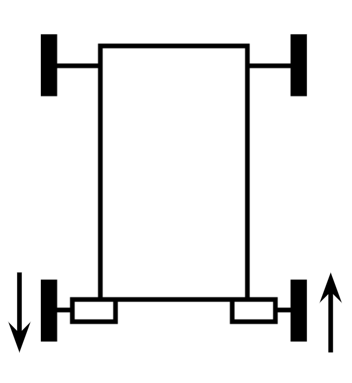
The diagram shows that if both motors moved “forward”, they would move in opposite directions since the motors are mounted in different orientations. We don’t want this, because moving both our motors “forward” would cause the robot to turn, instead of going forward.
To fix this, we can reverse the direction of our left motor in the init section of our code.
Now, once the init code runs, the directions of motors will be set so that “forward” for each motor will move the robot forward, as shown:

Control
Now that we have defined the “forward” direction of the motors, we can now control the motors in our loop code.
DC motors are controlled by setting the power value of the motor. A power value of 0 stops the motor, a power value of 1 runs the motor at 100% power (speed) forward, and a power value of -1 runs the motor at 100% power backwards. Power values can also be decimals. For instance, a power value of -0.3 would run the motor at 30% power backwards.
To test our motors, let’s simply run both of them at 30% power (note: we are going to run it at 30% rather than 100% because when you first test a motor, it is a good habit to run it at a slower speed in case something goes wrong). Add this code to the loop section of your program to accomplish this:
Now if you run your program, the robot should move forward at a fairly slow speed. Once you confirm that the motors are working, you can try to change the power values in the code to make the robot forward or backward at different speeds.
You can also try using different power values for each motor to cause the robot to turn (for example, setting the left motor to 1 and the right motor to -1 will cause the robot to turn right).
Gamepad Joysticks
Concept
Right now, our program simply sets our drive motors to 30% power and keeps them moving. Now, let’s make so that our driver (a student who controls the robot with the gamepad controller) can control when and how the drive motors move. The gamepad controller looks like this: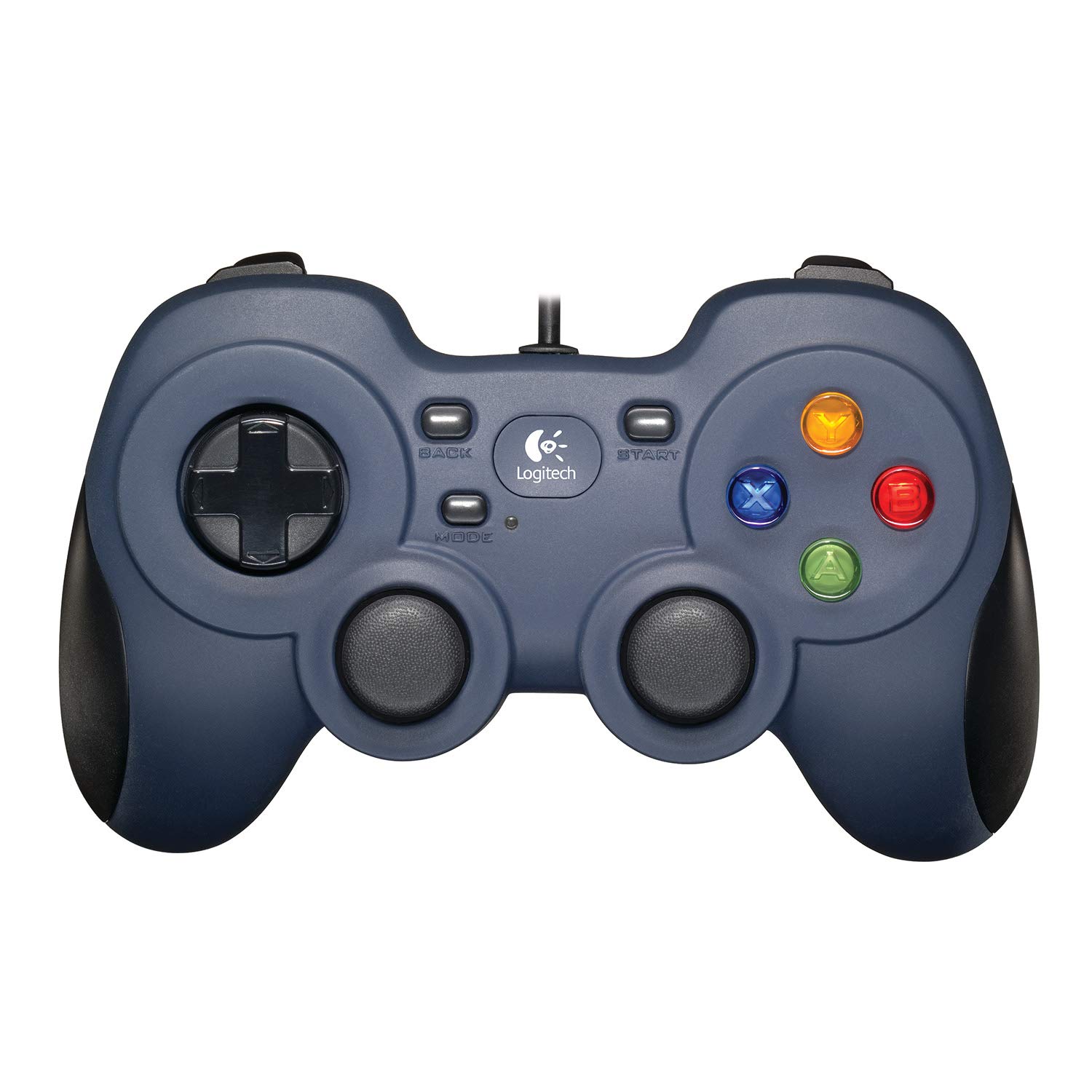
As you can see, the gamepad has a lot of different buttons and joysticks; all of which we can read input values from in our code. However, for our driving code, we are going to focus on the two joysticks (let’s call them left joystick and right joystick). When the driver moves a joystick in a certain direction, we can read these values:
As shown in this picture, a joysticks has two axis: the y axis (up and down) and the x axis (left and right). Each of these axis returns a value between -1 and 1 – similarly to motor powers. When the joystick is not being moved, both axes have a value of 0. When you move the joystick up and down, the value of the y axis changes. When you move the joystick left and right, the value of the x axis changes.
Below is an interactive widget that simulates a joystick. Click and drag the circle in the center to see how moving the joystick affects the y and x axis values.
x axis value: 0
y axis value: 0
Notice how when the joystick is tilted all the way forward, the y-axis returns -1. This is the opposite of what one would expect, since a value of -1 would move a motor backwards, not forwards. As a result, we will almost always negate y-axis values in our code so that tilting forward returns 1 instead of -1. This will be explained more later in this guide.
Code
Now let’s change our code from earlier so that the driver can control the motor powers with the gamepad joysticks. There are many different ways that a driver can control a robot, but the simplest one is called tank drive. In tank drive, moving the left joystick up and down (the y-axis) controls the left motor, and moving the right joystick up and down controls the right motor.
This is fairly simple to code, since we can just directly use the y-axis values from our joysticks:
left.setPower(-gamepad1.left_stick_y);
right.setPower(-gamepad1.right_stick_y);
Notice that there is a negative symbol (-) in front of each joystick value in the code. This is because, as mentioned earlier, the y-axis returns -1 when the joystick is pushed forward, rather than 1 as you may expect. To resolve this, the negative symbol in the code (which is known as a “negate” operation) reverses the value so that forward returns 1.
Also note that we use “gamepad1” in the code to indicate that we are targeting the “first” gamepad. Every time you plug your gamepad into your phone, you must press the “A” and “Start” buttons on the gamepad at the same in order for the phone to recognize it as the “first” gamepad.
A second gamepad can be configured by plugging it in through a USB Hub and pressing the “B” and “Start” buttons at the same time. You can use this joystick in your code by using “gamepad2”.
If you run this new code on your robot, the robot stay still if you are not touching the gamepad. If you tilt the left stick forward and backwards, it should move the left side of the robot. The right stick should do the same for the right side of the robot, and tilting both sticks forward should move the entire robot forward! You now should have a fully drive-able robot.
If your code is not functioning as expected, you can compare your code to the “full code” provided at the end of this guide. Every FTC programming guide on this website will have the full code at the end for convenience.
import com.qualcomm.robotcore.eventloop.opmode.LinearOpMode;
import com.qualcomm.robotcore.eventloop.opmode.TeleOp;
import com.qualcomm.robotcore.hardware.DcMotor;
import com.qualcomm.robotcore.hardware.DcMotorSimple;

@TeleOp(name="MyOpModeName")
public class MyOpModeName extends LinearOpMode {
  private DcMotor left;
  private DcMotor right;

  @Override
  public void runOpMode() {
    left = hardwareMap.dcMotor.get("left");
    right = hardwareMap.dcMotor.get("right");

    // Put initialization blocks here.
    left.setDirection(DcMotorSimple.Direction.REVERSE);
    waitForStart();
    if (opModeIsActive()) {
      // Put run blocks here.
      while (opModeIsActive()) {
        // Put loop blocks here.
        left.setPower(-gamepad1.left_stick_y);
        right.setPower(-gamepad1.right_stick_y);
      }
    }
  }
}